Getting started with Montic W04 - CH32V208
The Montic W04 is a development board compatible with the Pro Micro form factor. It uses WCH’s CH32V208 low-power Bluetooth SoC processor, which integrates a single-core high-performance 32-bit RISC-V CPU and supports Bluetooth® 5 (LE) wireless connectivity. It is an excellent first board for exploring wireless applications.
Hardware overview
The Montic W04 is based on the WCH CH32V208 processor, a 32-bit RISC-V low-power Bluetooth SoC. It supports clock frequencies up to 144MHz, provides 64KB of SRAM, and up to 480KB of Flash. In addition to Bluetooth wireless applications, the Montic W04 also supports a CAN controller, a USB 2.0 full-speed host/device controller, and common peripherals like UART, SPI, I2C, and ADC.
The board also includes 16Mbits (2MBytes) of onboard Flash storage, a WS2812 addressable RGB LED that supports 256 brightness levels and 16 million colors, and a tactile switch. Our goal is to keep the board as compact as possible while offering enough interaction options.
For power, the board uses a USB-C connector so you can rely on the USB-C cables you already have. The Montic W04 also retains battery power support and includes onboard charge and discharge circuitry.
On the IO side, aside from two additional power pins, the Montic W04 keeps IO compatibility with the Pro Micro while the CH32V208 provides rich peripheral capabilities and enhanced I/O ports.
Pinout diagram
Before you start using the product, take a moment to understand the pinout. Montic keeps the Pro Micro form factor and compatibility with a few adjustments. There are 26 pins in total. The detailed pinout diagram will be provided below.
TODO:
- Clarify which pins are used and how they are multiplexed.
- Provide a complete pinout diagram that explains pin multiplexing (similar to the example below).

Microcontroller (MCU)
The Montic W04 uses WCH’s CH32V208, a 32-bit processor based on the RISC-V architecture. The CPU core is QingKe V4C with instruction set extensions I, M, A, and C.
| Model | Instruction set | Hardware stack depth | Interrupt nesting level | Table-free interrupt channels | Pipeline | Vector table mode | Extended instructions (XW) | Number of memory protection regions |
|---|---|---|---|---|---|---|---|---|
| QingKe V4A | RV32IMAC | 2 | 2 | 4 | 3 | Address/Instruction | ❌ | 4 |
| QingKe V4B | RV32IMAC | 2 | 2 | 4 | 3 | Address/Instruction | ✔ | 4 |
| QingKe V4C | RV32IMAC | 2 | 2 | 4 | 3 | Address/Instruction | ✔ | 4 |
| QingKe V4F | RV32IMACF | 3 | 8 | 4 | 3 | Address/Instruction | ✔ | 4 |
Instruction set notes:
- I: Supports integer operations with 32 integer registers
- M: Supports integer multiplication and division instructions
- A: Supports atomic instructions
- C: Supports 16-bit compressed instructions
- F: Supports single-precision floating-point operations with 32 floating-point registers
- XW: QingKe processors add an extended RISC-V instruction set for additional 16-bit compressed instructions on byte and half-word operations. Use the MRS compiler or toolchains provided with it to enable these instructions.
Product features
| Item | Specification |
|---|---|
| CPU frequency | Up to 144MHz |
| Flash (Bytes) | 128KB or 480KB(1) |
| SRAM (Bytes) | 64KB |
| USB Full Speed Device (USBD) | 1 x USB 2.0, supports USB FS 12Mbps and Low-speed 1.5Mbps modes(2) |
| USB Full Speed Host (USBHD) | 1 x USB 2.0 Host |
| Bluetooth® 5 (LE) | Supports BLE 5.3(3) |
| CAN | 1x CAN 2.0A and 2.0B(2) |
| GPIO ports | 53 |
| Other peripheral interfaces | 4x UART / 2x SPI / 2x I2C / ADC / 5x TIMER / 2x WDT |
(1) The Flash size refers to the zero-wait operation region R0WAIT; the non-zero-wait region is 480K - R0WAIT.
(2) The USBD and CAN controllers share a dedicated 512-byte SRAM area for data transmission and reception. When using USBD and CAN simultaneously, allocate this shared area carefully to avoid data conflicts.
(3) The Bluetooth® 5 (LE) protocol stack is provided by WCH as a binary library. Source code is not provided; only SDK API documentation is available. See the Resources section for more details.
Low-power modes
The CH32V208 supports three low-power modes, allowing you to balance low power consumption, short startup time, and multiple wake-up events based on your scenario. From the perspective of processor, peripherals, and voltage regulator behavior, the modes are:
- Sleep mode: The core stops running while all peripherals (including core-private peripherals) continue to run.
- Stop mode: All clocks stop. After wake-up, the system continues execution.
- Standby mode: All clocks stop. After wake-up, the microcontroller resets (power-on reset).
| Mode | How to enter | Wake-up source | Clock impact | Voltage regulator |
|---|---|---|---|---|
| Sleep | WFI/WFE | Any interrupt or wake-up event | Core clock off; other clocks unaffected | Normal |
| Stop | Set SLEEPDEEP to 1, clear PDDS to 0, then WFI/WFE | Any external interrupt/event (configured in the external interrupt registers) | HSE, HSI, PLL, and peripheral clocks are off | Normal when LPDS=0; low-power when LPDS=1 |
| Standby | Set SLEEPDEEP to 1, set PDDS to 1, then WFI/WFE | Rising edge on WKUP pin, RTC alarm event, NRST pin reset, or IWDG reset. Note: Any event can wake the system, but it resets after wake-up. | HSE, HSI, PLL, and peripheral clocks are off | Off |
For more information on the QingKe V4C processor and CH32V208, see the Resources section.
Onboard Flash
The Montic W04 includes 2MBytes of Flash to expand the ROM space. It communicates via the CH32V208’s Serial Peripheral Interface (SPI) memory interface.
For more details, refer to the Flash datasheet:
ZD25WQ16B datasheet
Power
The Montic W04 can be powered in multiple ways: USB-C, lithium battery, or direct power input. Thanks to the onboard charge/discharge circuitry, you can charge a lithium battery via USB-C or other power inputs.
Supported power inputs and their maximum voltage/current:
| USB-C | VBUS pin | Lithium battery | |
|---|---|---|---|
| Max voltage (V) | 5 | 5 | 3.3 |
| Max current (mA) | 500 | ? | ? |
USB-C
The USB-C port is the most convenient power option. You can use it to provide power to the device or charge the lithium battery connected to the board.
Lithium battery
A dedicated JST 1.25mm connector is provided for lithium batteries. The circuit supports charging while the battery is connected.
VBUS pin
When using an external power supply, connect to the VBUS pin (5V). Ensure the external power supply can deliver sufficient current.
Buttons and LED
| Component | Quantity | Purpose |
|---|---|---|
| WS2812 RGB LED | 1 | Addressable RGB LED for status indication or lighting effects |
| BOOT button | 1 | Boot mode selection |
Board dimensions
TODO: add a dimensional drawing including IO spacing and layout.
Getting started
CH32V208 and Montic W04 products
CH32V20x Series Development Documentation
More resources
- OpenWCH on GitHub: Collections of CH32V series documents, code samples, and demos.
- ch32-rs: Community Rust support for WCH 32-bit microcontrollers.
- platform-ch32v: PlatformIO support for the CH32V/F series.
- WCH-Link debugger and WCH-Link User Manual.
- WCHISPTool for USB ISP programming and WCHISPTool_CMD for command-line use.
Development environment
Using CH32V20x EVT
- Install the
WCH-ISP-Tool(Windows) orwchisp(macOS/Linux). - Download the reference examples from CH32V20xEVT, which include CH32V208 application samples and documentation, including BLE stack manuals and BLE OTA guidance.
- Install MounRiver Studio (Embedded RISC-V IDE) for Windows or Linux, or use the macOS Toolchains package from the same site.
- Ensure you have a USB-C data cable and the Montic W04 development board.
The CH32V20xEVT package contents include:
CH32V20x_List.txt
CH32V20x_List_EN.txt
Directory
EXAM/
DirectoryAPPLICATION/
DirectoryUSBPD/
- …
DirectoryWS2812_LED/
- …
DirectoryBKP/
- …
DirectoryBLE/
- …
DirectoryCAN/
- …
DirectoryCRC/
- …
DirectoryDMA/
- …
…
DirectoryUSB/
- …
DirectoryWWDG/
- …
Directory
PUB/
- …
Set up MounRiver Studio
-
Download and install MounRiver Studio. On the download page, choose the Windows version. Important: download the Embedded RISC-V IDE version.
-
Unzip the downloaded package, open the extracted directory, and run the installer (for example,
MounRiver_Studio_V192_Setup.exe). Follow the prompts to complete installation. -
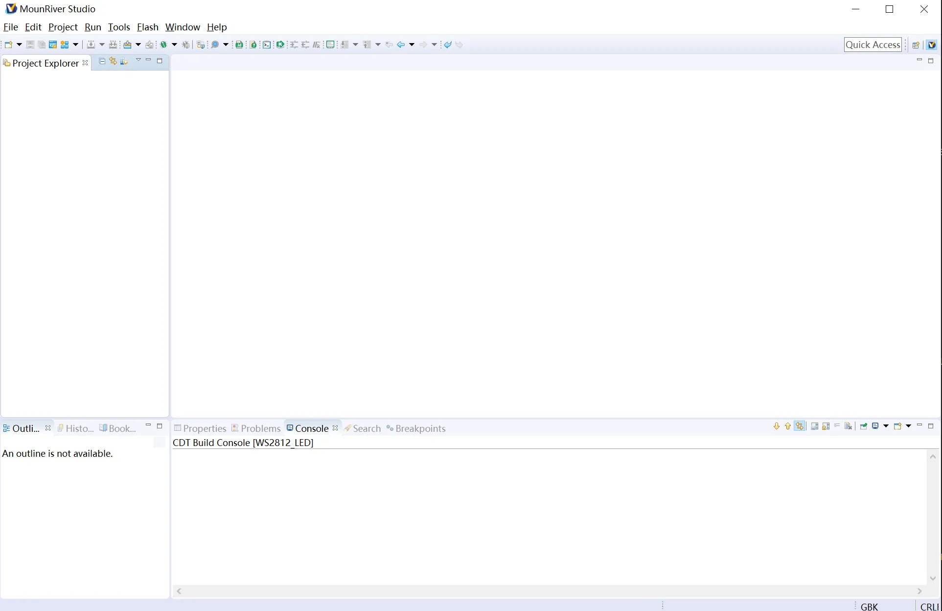
Launch MounRiver Studio.
After installation, start MounRiver Studio from the desktop shortcut or Start Menu. You should see a screen similar to the one below.
-
Install prerequisite packages. To build with the ESP-IDF, you need the following packages (commands differ by distribution):
- Ubuntu and Debian:
Terminal window sudo apt-get install git wget flex bison gperf python3 python3-pip python3-venv cmake ninja-build ccache libffi-dev libssl-dev dfu-util libusb-1.0-0- CentOS 7 & 8:
Terminal window sudo yum -y update && sudo yum install git wget flex bison gperf python3 cmake ninja-build ccache dfu-util libusbx -
Download and install Visual Studio Code.
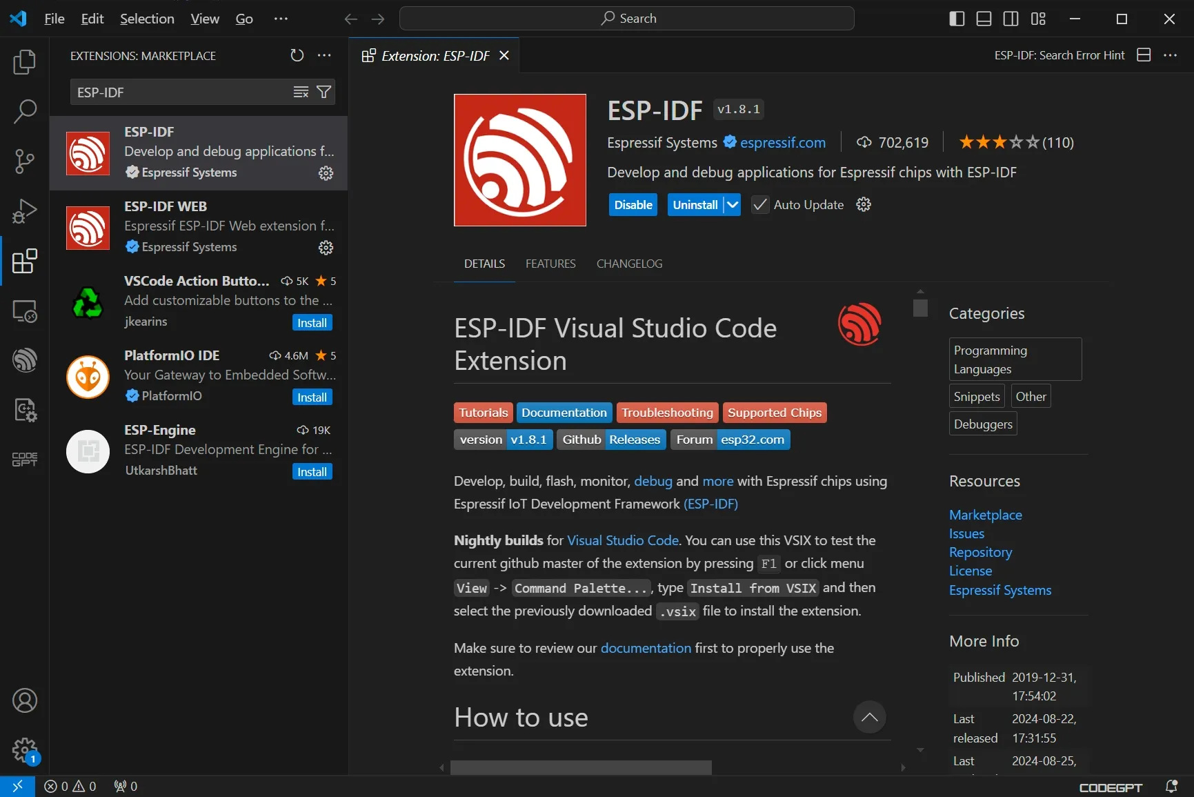
-
Search for and install the ESP-IDF Extension in VS Code.
-
Configure ESP-IDF.
In VS Code, select
View>Command Paletteor pressCtrl-Shift-P, then enterconfigure esp-idf extension. Choose ESP-IDF: Configure ESP-IDF Extension. You can also choose where to save the configuration during the setup wizard.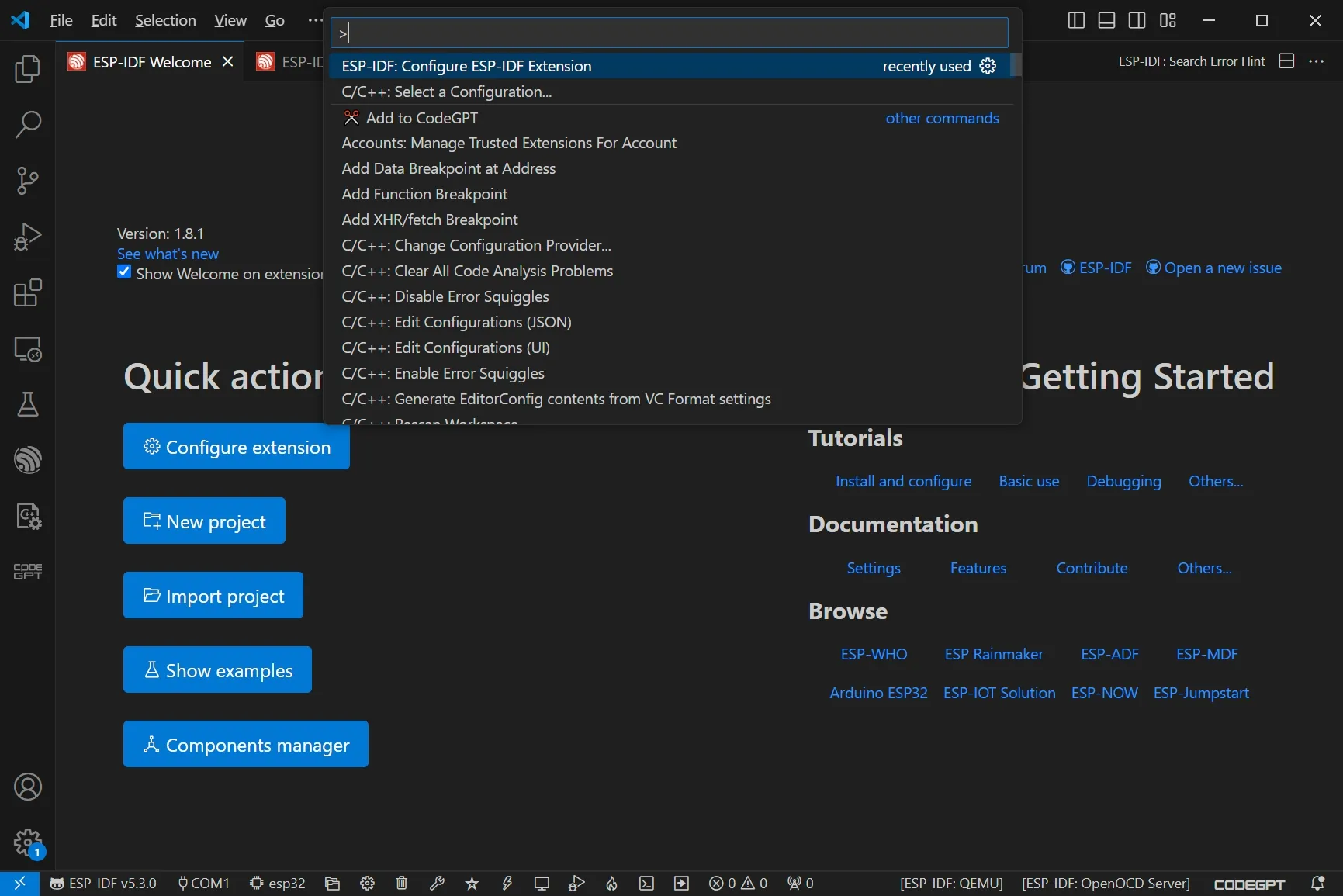
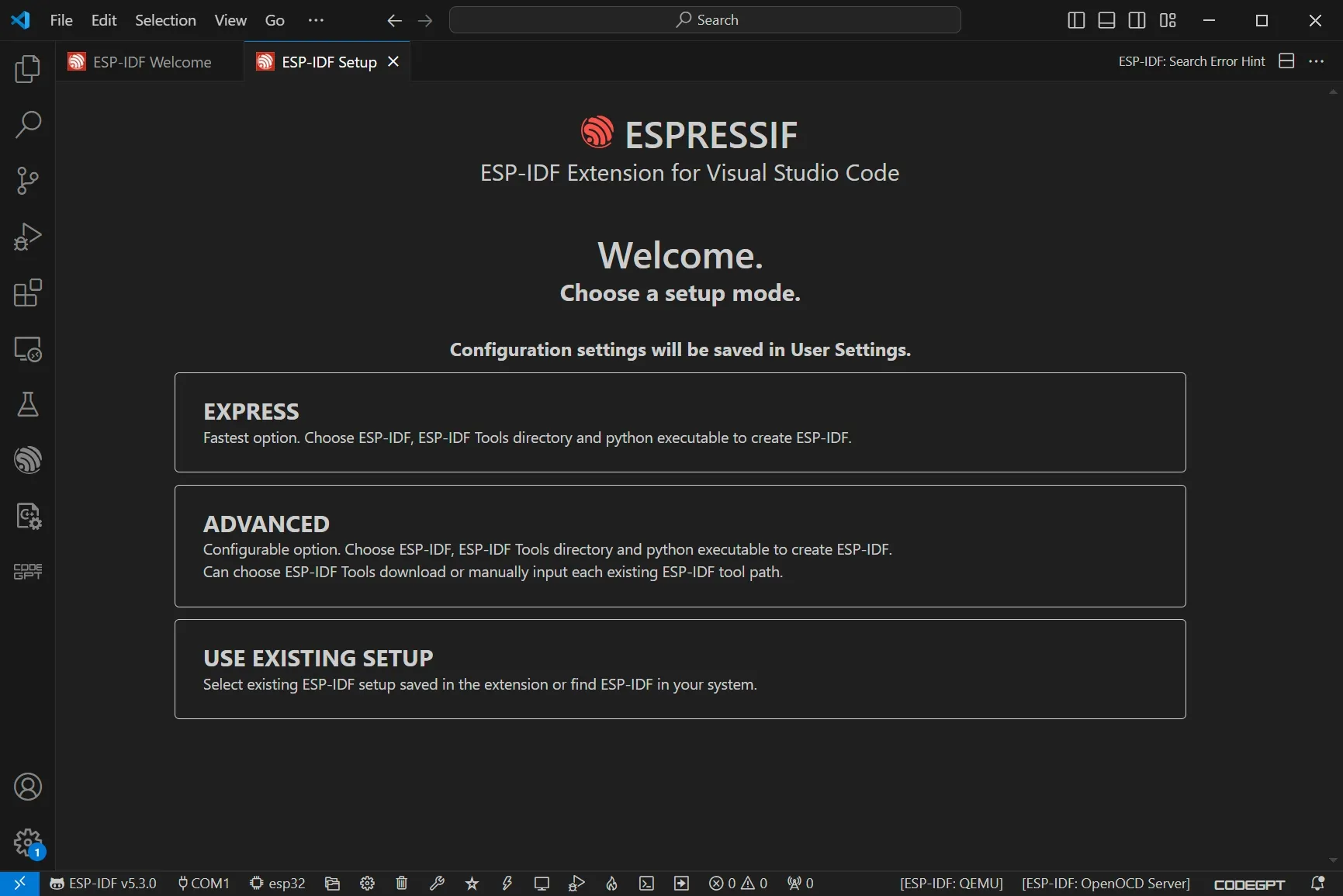
Choose the
Expressinstallation, select the latest release branch, and clickinstallto proceed automatically.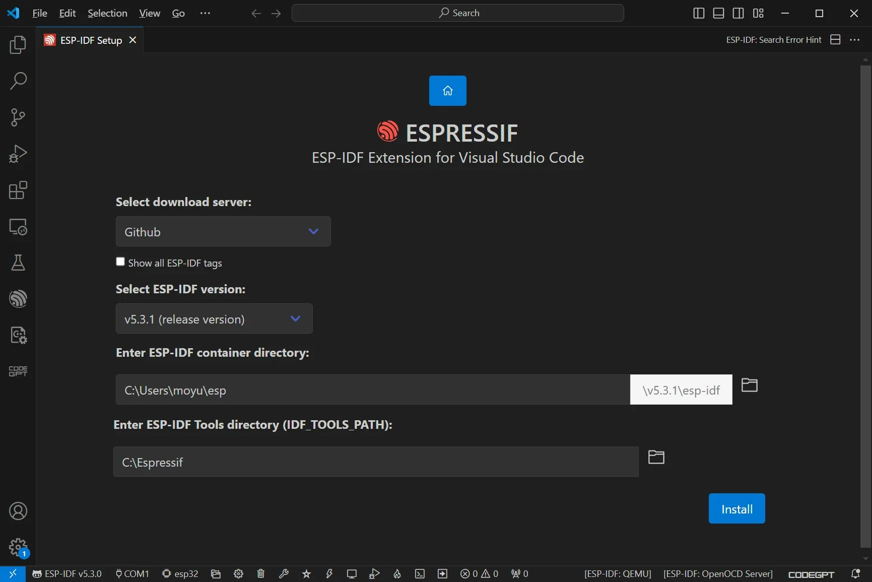
-
After installation, review the basic usage guide to learn how to configure the SDK, build, flash, and monitor your Espressif devices.
MounRiver Studio does not support macOS directly, but it offers Toolchains for macOS that can be downloaded from the MounRiver Studio website: MRS_Toolchain_MAC_V192.zip.
This Toolchains package includes GCC, OpenOCD, and WCHISPTool, supporting RISC-V assembly and GNU C compilation/linking. The debugger supports chip erase, programming, verification, and debugging.
We also recommend ch32v003fun, an open-source minimal stack for WCH processors such as the ch32v003 and the broader ch32v/x series, including the CH32V208. It can be paired with Community-PIO-CH32V to integrate ch32v003fun into VS Code for easier use.
Blink Demo
After setting up the software development environment, let’s create a program to blink the RGB LED.
-
Load the
WS2812_LEDexample.After installation, open MounRiver Studio and choose
File -> Load.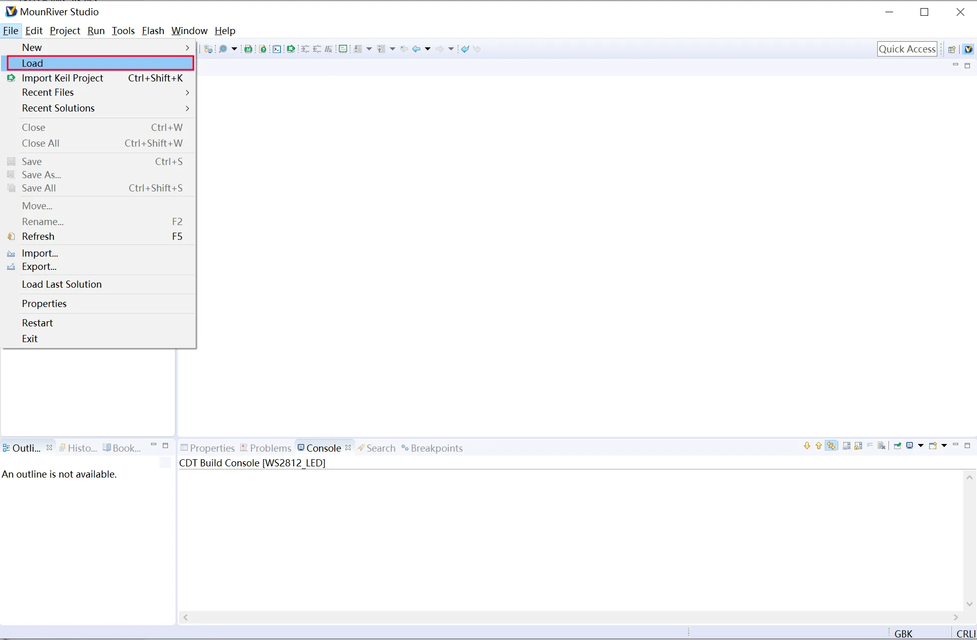
-
Navigate to the
EXAM/APPLICATION/WS2812_LEDfolder.In the load dialog, browse to the
EXAM/APPLICATION/WS2812_LEDdirectory from the CH32V20xEVT package.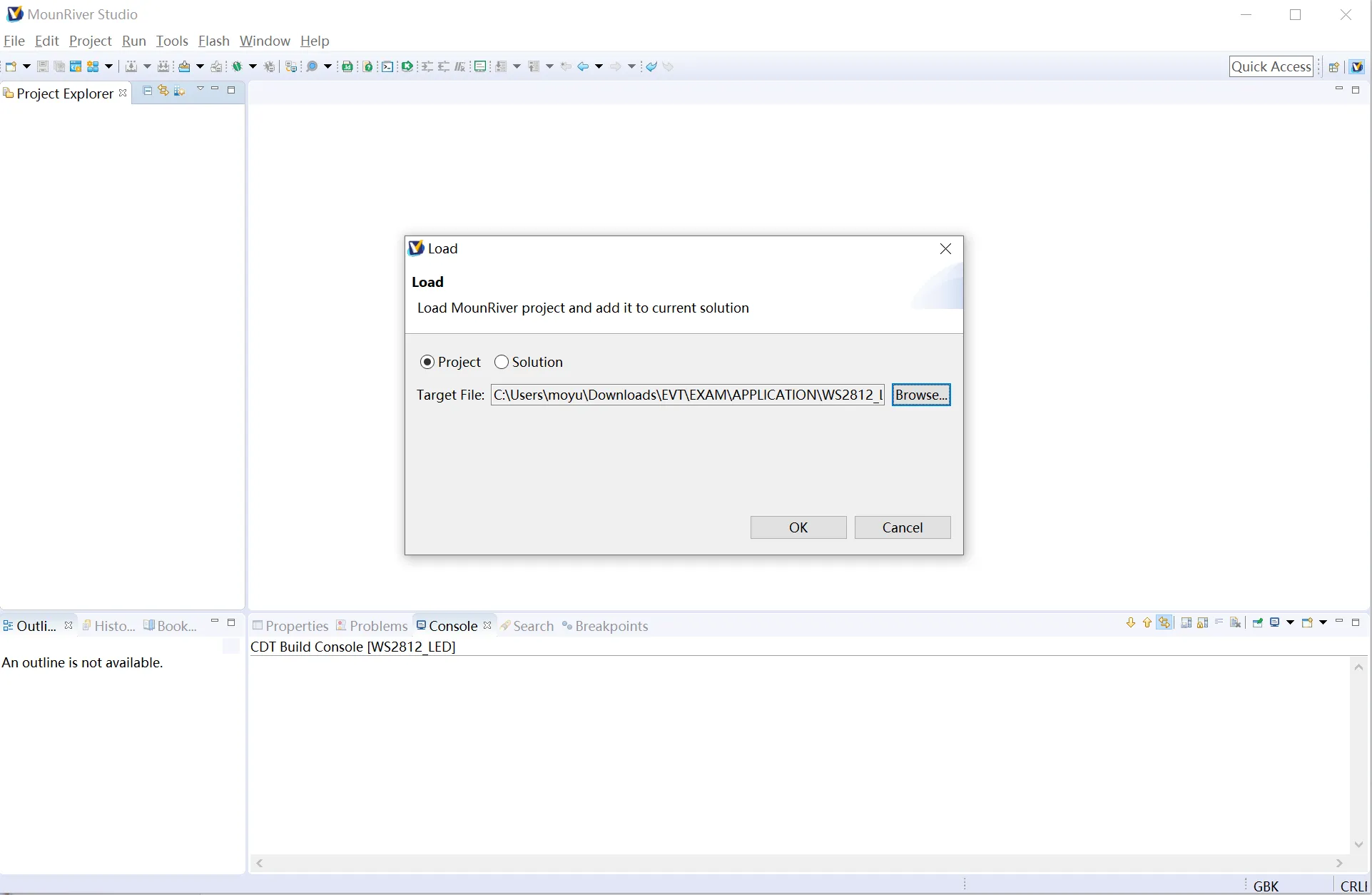
-
Select the
MDKfolder insideWS2812_LED.Choose the Keil (MDK) project folder to open the example.
-
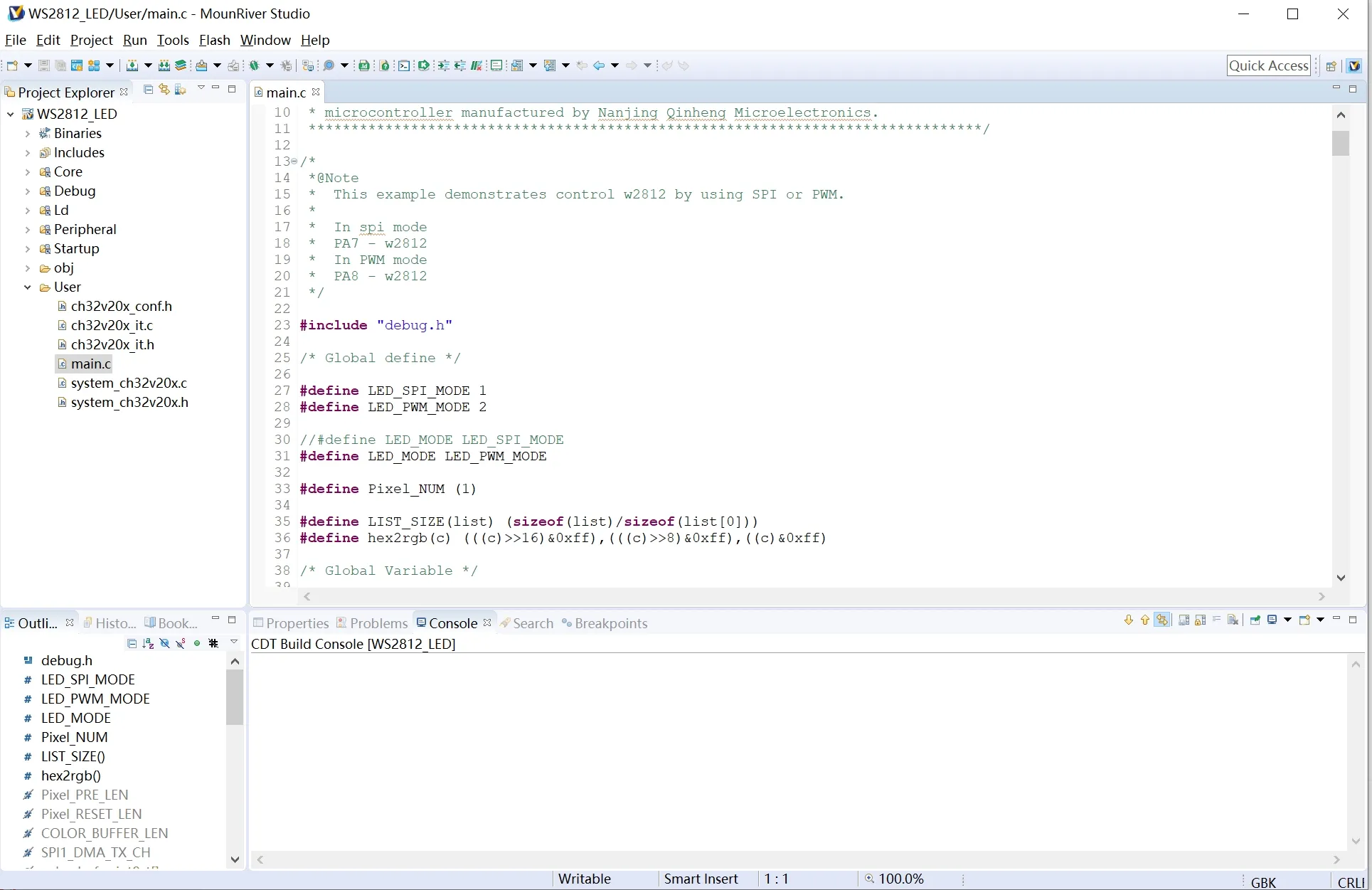
Flash the example onto the Montic W04.
With your board connected, click
Downloadto flash the firmware. The onboard WS2812 LED should start blinking, confirming everything works.
Develop with Arduino
-
Install the Arduino IDE.
Download and install the latest Arduino IDE for your operating system.
-
Add CH32V Arduino board support.
The CH32V Arduino core is community-maintained. Follow the instructions in the arduino_core_ch32 repository to add the CH32V board manager URL to the Arduino IDE, then install the board package.
-
Select the Montic W04 board.
Go to
Tools -> Board, chooseCH32V EVT Boards Support > H32V20x, then inTools -> Board Select, pickMontic W04 CH32V208CB. -
Verify the board definitions.
After installing, check the
boards.txtand pin definitions to confirm the Montic W04 configuration is present. If you need to add the board manually, append the following entry topackages/CH32V-dev/Ch32v-Mac/CH32V/core/riscv/boards.txt(path may vary by OS):Board definition snippet
##############################################################Montic_W04_CH32V208CB.name=Montic W04 CH32V208CBMontic_W04_CH32V208CB.cdcoptions=CDC disabled,CDC USBMontic_W04_CH32V208CB.upload.protocol=daplinkMontic_W04_CH32V208CB.upload.maximum_size=475136Montic_W04_CH32V208CB.upload.speed=115200Montic_W04_CH32V208CB.upload.wait_for_upload_port=falseMontic_W04_CH32V208CB.vid.0=0x1A86Montic_W04_CH32V208CB.pid.0=0x8010Montic_W04_CH32V208CB.vid.1=0x1A86Montic_W04_CH32V208CB.pid.1=0x8010Montic_W04_CH32V208CB.build.mcu=ch32v20xMontic_W04_CH32V208CB.build.core=ch32v20xMontic_W04_CH32V208CB.build.variant=Montic_W04Montic_W04_CH32V208CB.build.variant_system_lib=stdPeriphMontic_W04_CH32V208CB.build.board=Montic_W04Montic_W04_CH32V208CB.build.series=CH32V20xMontic_W04_CH32V208CB.build.product_line=CH32V208Montic_W04_CH32V208CB.build.chip=CH32V208CBMontic_W04_CH32V208CB.build.flash_ld=ld/Link.ldMontic_W04_CH32V208CB.build.led=PC13Montic_W04_CH32V208CB.build.vusb_pin=PC2Montic_W04_CH32V208CB.build.vbus_pin=PB8Montic_W04_CH32V208CB.build.pvdin_pin=PC15Montic_W04_CH32V208CB.build.neopixel_pin=PA2Montic_W04_CH32V208CB.build.usb_manufacturer=MonticMontic_W04_CH32V208CB.build.usb_product=W04Montic_W04_CH32V208CB.build.board_name=Montic W04Montic_W04_CH32V208CB.upload.maximum_ram_size=65536Montic_W04_CH32V208CB.build.openocdscript=ch32v20x_openocd.cfgMontic_W04_CH32V208CB.menu.clock.144=System Clock 144MHzMontic_W04_CH32V208CB.menu.bootloader.0=No bootloaderMontic_W04_CH32V208CB.menu.timer.0=DefaultMontic_W04_CH32V208CB.menu.usb.0=MSC+CDCMontic_W04_CH32V208CB.menu.usb.1=CDCMontic_W04_CH32V208CB.menu.upload_method.0=via WCHISPMontic_W04_CH32V208CB.menu.upload_method.0.upload.tool=wlinkuploadMontic_W04_CH32V208CB.menu.upload_method.0.build.BUILD_UPLOADER=wlinkMontic_W04_CH32V208CB.menu.upload_method.0.build.BUILD_CDC=CDCMontic_W04_CH32V208CB.menu.upload_method.0.build.upload_flags=--name Montic W04 --chip ch32v208cb --reset 20 --path ./tools/wlinkMontic_W04_CH32V208CB.menu.upload_method.0.upload.protocol=wlinkMontic_W04_CH32V208CB.menu.upload_method.0.upload.params.verbose=-vMontic_W04_CH32V208CB.menu.upload_method.0.upload.params.quiet=-qMontic_W04_CH32V208CB.menu.upload_method.0.upload.pattern="{build.path}/{build.project_name}.elf"Montic_W04_CH32V208CB.menu.upload_method.0.upload.maximum_size=45571If you are using macOS, the paths will differ; adjust accordingly. After adding the board definition, update
pins_arduino.hundervariants/Montic_W04with the W04 pin assignments:Pin definition snippet
#ifndef Pins_Arduino_h#define Pins_Arduino_h#include <stdint.h>#include "soc/soc_caps.h"#define PIN_RGB_LED 15// BUILTIN_LED can be used in the Arduino API digitalWrite() like Blink.inostatic const uint8_t LED_BUILTIN = SOC_GPIO_PIN_COUNT + PIN_RGB_LED;#define BUILTIN_LED LED_BUILTIN#define LED_BUILTIN LED_BUILTIN// RGB_BUILTIN and RGB_BRIGHTNESS can be used in the Arduino API neopixelWrite()#define RGB_BUILTIN LED_BUILTIN#define RGB_BRIGHTNESS 64static const uint8_t TX = 29;static const uint8_t RX = 30;static const uint8_t SDA = 33;static const uint8_t SCL = 34;static const uint8_t SS = 13;static const uint8_t MOSI = 14;static const uint8_t MISO = 15;static const uint8_t SCK = 8;static const uint8_t A0 = 9;static const uint8_t A1 = 10;static const uint8_t A2 = 11;static const uint8_t A3 = 12;static const uint8_t D0 = 33;static const uint8_t D1 = 34;static const uint8_t D2 = 31;static const uint8_t D3 = 32;static const uint8_t D4 = 35;static const uint8_t D5 = 36;static const uint8_t D6 = 17;static const uint8_t D7 = 16;static const uint8_t D8 = 13;static const uint8_t D9 = 14;static const uint8_t D10 = 15;static const uint8_t D11 = 8;#endif /* Pins_Arduino_h */ -
Restart the Arduino IDE and select Montic W04 as the target board.
Go to
Tools -> Boardand choose Montic W04. You can also search directly in the board dropdown. If you encounter setup issues, refer to the arduino_core_ch32 repository for the latest guidance and support. -
Upload your first sketch.
Click
Uploadto compile and flash your code. Once complete, the board is ready for use.
Serial demo
Let’s use Arduino to demonstrate serial output. This demo uses the Adafruit TinyUSB Library bundled as a Git submodule of arduino_core_ch32.
-
Create a new Arduino sketch.
With
CH32V EVT Boards Support > H32V20xselected andMontic W04 CH32V208CBchosen underTools -> Board Select, paste the following code:#include <Arduino.h>#include <Adafruit_TinyUSB.h> // required for USB Serialvoid setup () {}void loop () {delay(1000);Serial.println("1");delay(1000);Serial.println("2");}Save the sketch to a folder you can easily locate for later compilation outputs.
-
Compile and upload the program.
Click
Verifyin the Arduino IDE to ensure the code compiles.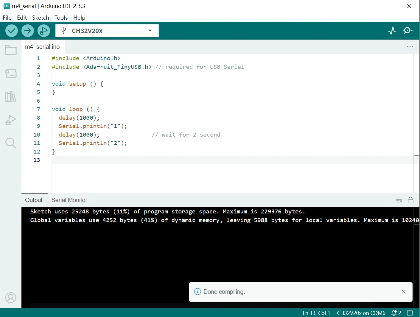
For the first upload, use the WCP In-system Programmer (ISP) as described in the Blink Demo step 4. Use
Sketch -> Export Compiled Binaryto obtain the.hexfile. -
View serial output.
After uploading, open
Tools -> Serial Monitorin the Arduino IDE, set baud rate to 115200, and observe the printed output.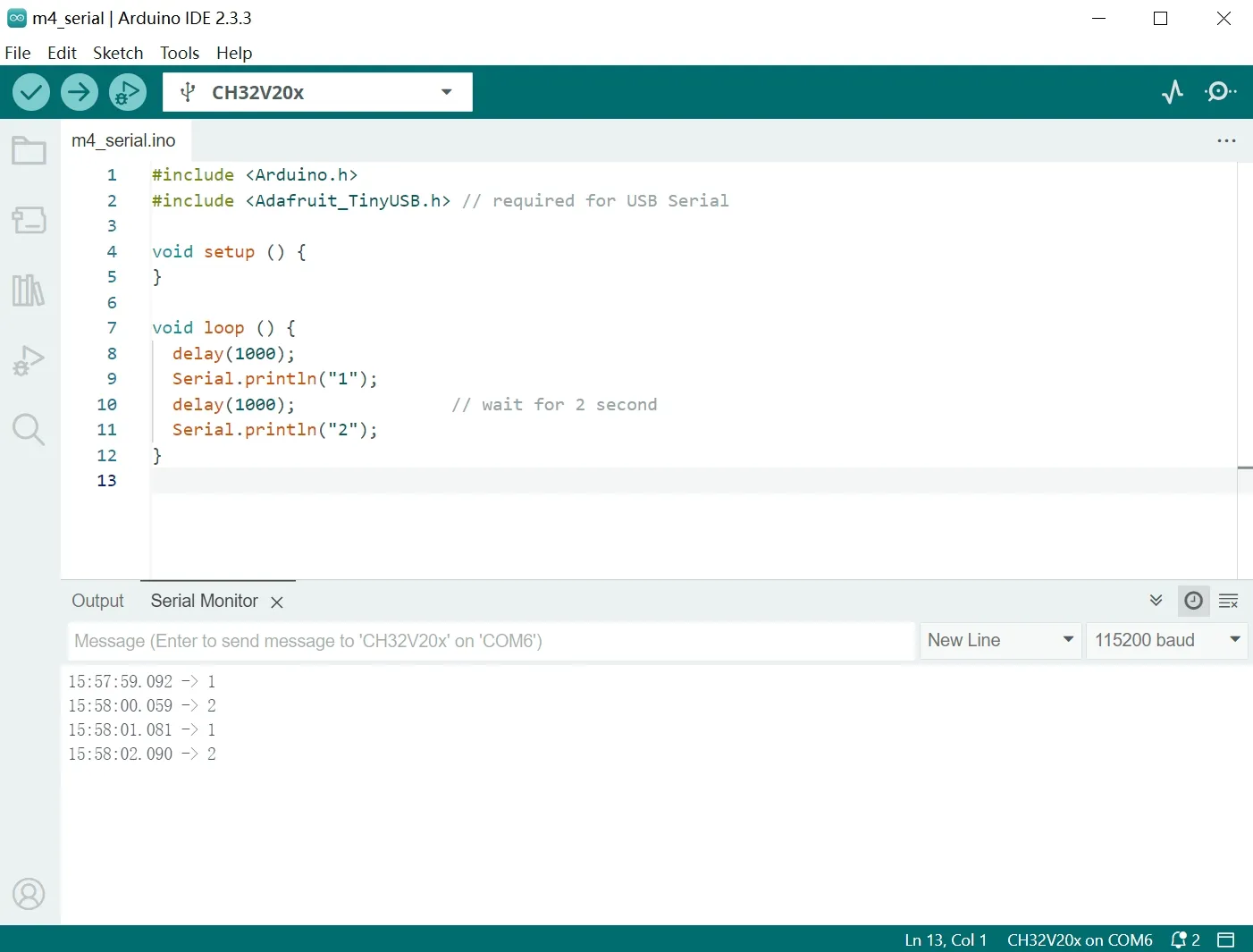
Resources and guides
Resources
-
Montic W04 design files:
-
Documents: DataSheet, Manual, etc. DS for “DataSheet”, RM for “Reference Manual”.
- WCH official download center English Website/Chinese site.
- CH32V208 DataSheet: Datasheet/Chinese datasheet.
- CH32FV2x_V3xRM Reference Manual: Reference manual/Chinese manual.
- QingKe RISC-V V4 CPU manual (English): QingKeV4 manual/QingKeV4 processor manual
- CH32V20xEVT: Application examples and documents for CH32V208, including BLE software stack manuals, BLE OTA, and more.
-
Toolchains
- MounRiver Studio - WCH’s official IDE supporting Windows, Linux, and macOS.
- Debugger probes:
- USB ISP Programmer:
- WCHISPTool_Setup.exe.
- WCHISPTool_CMD.ZIP for command line on Linux, macOS, and Windows.
- ch32v003fun: Open-source minimal stack for the ch32 line of WCH processors (including CH32V208).
- platform-ch32v: PlatformIO for the CH32V/F series maintained by the community.
- Bootloader:
- WCH-UF2, a UF2 bootloader for WCH’s 32-bit microcontrollers by ArcaneNibble.
-
GitHub Organizations
- OpenWCH - organized by MCU series; includes documentation, code, and demos.
- Arduino supported by OpenWCH (CH32V208 not supported yet).
- Another Arduino supported by the CH32 RISC-V User Group (CH32V208 not supported yet).
- OpenOCD (Binary) supported by OpenWCH.
- CH32-RS: Rust support projects for WCH 32-bit microcontrollers by the community.
- Community-PIO-CH32V: PlatformIO for the CH32V/F series.