Getting started with Montic W02 - ESP32-C6
The Montic W02 is a development board compatible with the Pro Micro form factor. It features Espressif’s ESP32-C6 Wi-Fi/Bluetooth processor, integrating a single-core high-performance RISC-V 32-bit processor with support for up to 160MHz, as well as an additional low-power processor with up to 20MHz support. It also supports various wireless functions, including 2.4GHz Wi-Fi6 (802.11ax), Bluetooth® 5(LE), Zigbee, and Thread(802.15.4). This makes it an ideal first development board for exploring wireless applications.
The Montic W02 also comes with 64Mbits (8MBytes) of onboard Flash storage, a WS2812 addressable RGB LED supporting 256 levels of brightness and 16 million colors, and two tactile switches for Reset and BOOT functions. Our goal is to keep the board as compact as possible while providing sufficient interaction capabilities.
In terms of power, the board features a USB-C interface, allowing you to use your existing USB-C power cables without wasting resources. Additionally, the Montic W02 retains battery power capabilities and includes onboard charging and discharging circuits.
Regarding IO, apart from adding two power IOs, the Montic W02 maintains IO compatibility with the Pro Micro. Thanks to the ESP32-C6’s IO multiplexing capabilities, you can directly configure IO capabilities through software, supporting protocols such as ADC, GPIO, UART, SPI, I2C, PWM, 1-Wire, and more.
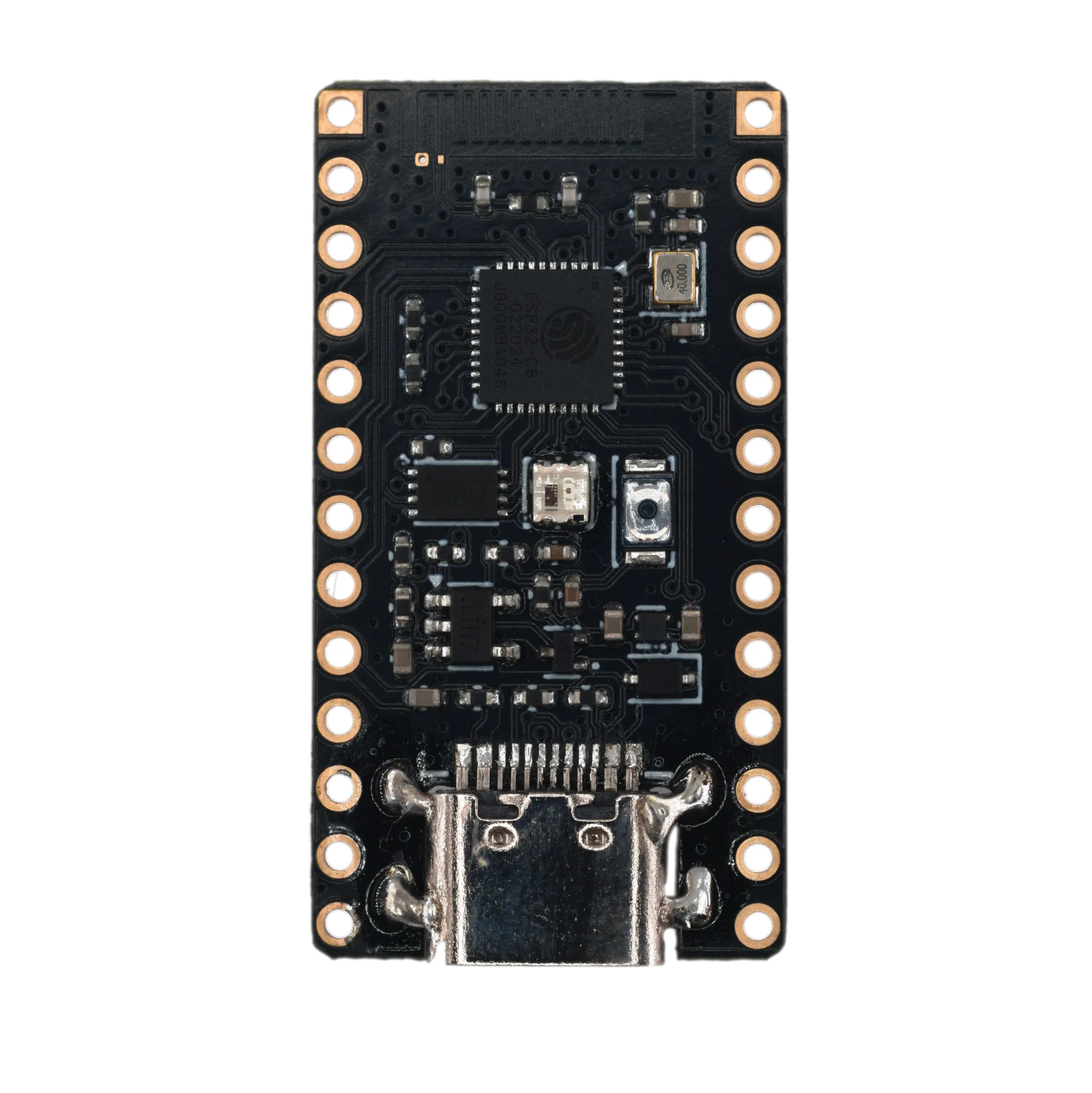
Hardware overview
The Montic W02 uses the ESP32-C6 in a QFN40 package rather than a module like the WROOM1. This keeps the board compact and compatible with the Pro Micro footprint while letting us choose different Flash options.
Beyond the ESP32-C6, the Montic W02 adds 8MBytes of Flash and a WS2812 addressable RGB LED. Because USB-C is widely adopted (and to minimize adapters), we use a USB-C connector for power and wired communication. If you use a lithium battery, the W02 also includes charging and discharging circuitry so USB can charge the battery.
Pinout diagram
Before using the product, review the pinout. Montic follows the Pro Micro layout with a few tweaks, totaling 26 pins. A detailed pinout diagram will be provided below.
TODO:
- Clarify which pins are used and how multiplexing is configured.
- Provide a complete pinout diagram explaining multiplexing (similar to the example below).

Microcontroller (MCU)
The Montic W02 uses the Espressif ESP32-C6 QFN40 (without integrated Flash). It has two 32-bit RISC-V processors using the RV32IMAC ISA with the following characteristics:
| Item | HP CPU | LP CPU |
|---|---|---|
| Architecture | 4-stage pipeline | 2-stage pipeline |
| Frequency | Up to 160 MHz | Up to 20 MHz |
| Instruction set | RV32IMAC | RV32IMAC |
| Interrupts | 28 vectored interrupts, 15 priority levels | Interrupt support |
| HW breakpoints/watchpoints | 4 hardware breakpoints/watchpoints | 2 hardware breakpoints/watchpoints |
| Debug interface | JTAG; supports RISC-V Debug Spec v0.13 and Trace v1.0 | JTAG; supports RISC-V Debug Spec v0.13 |
| Multiplier/divider | 32-bit multiplier and divider | 32-bit multiplier and divider |
| On-chip memory | 512 KB SRAM for data and instructions | 16 KB SRAM shared with HP CPU; retained in deep sleep |
| Other features | 16 PMP/PMA regions; hardware breakpoint debug support | Runs during deep sleep to manage low-power tasks |
| Scenarios | Complex tasks, high-performance applications | Assists the HP CPU or handles low-power operations |
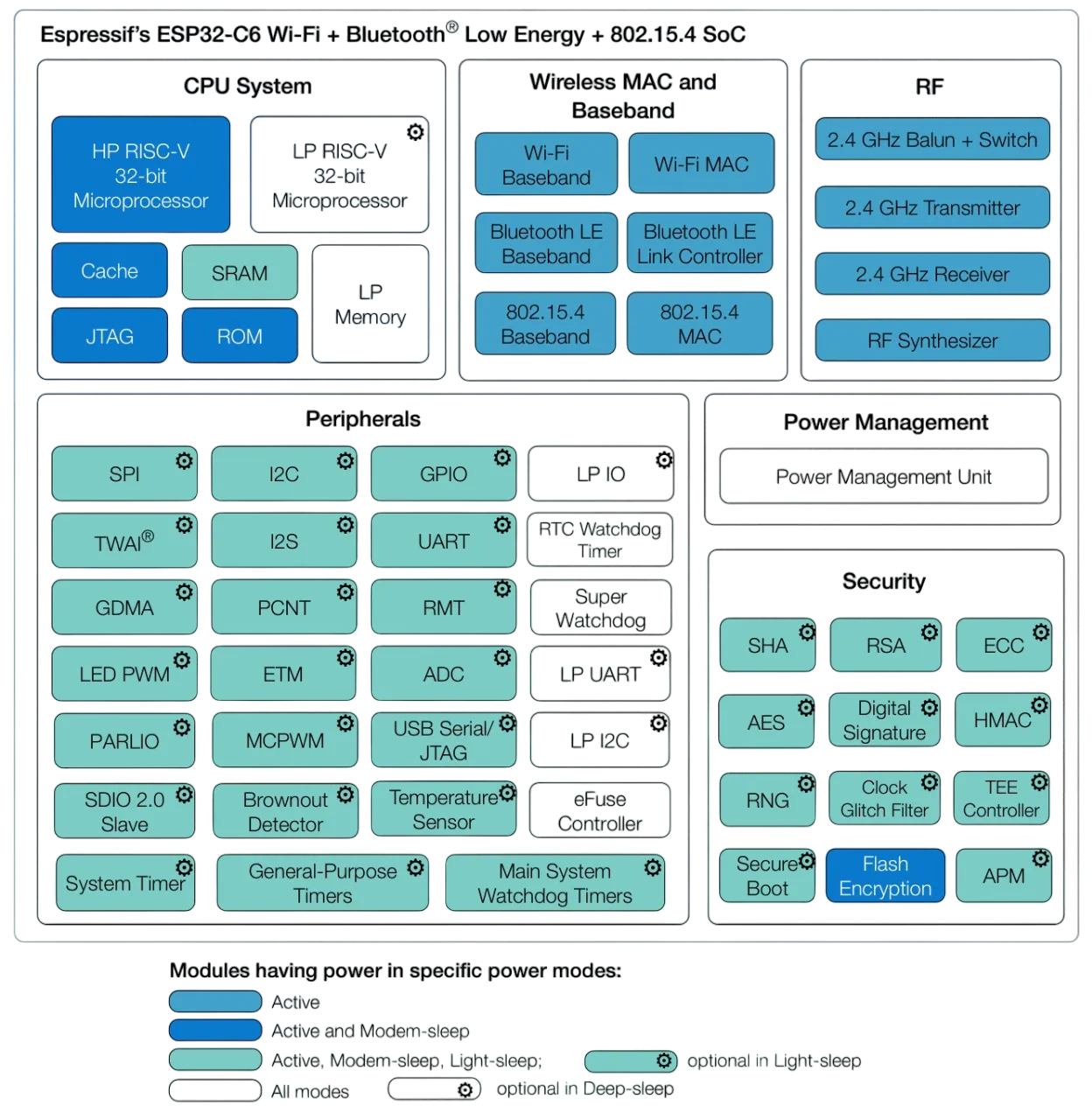
Wireless features
The ESP32-C6 integrates Wi-Fi, Bluetooth Low Energy, and 802.15.4, with Wi-Fi and Bluetooth sharing a single antenna.
The ESP32-C6 follows the IEEE 802.11 b/g/n/ax Wi-Fi MAC stack, supporting Basic Service Set (BSS) STA and SoftAP operation under Distributed Coordination Function (DCF). It supports Infrastructure BSS Station , SoftAP , Station + SoftAP , and promiscuous modes. Power management minimizes host interaction to extend active operation.
- Supports IEEE 802.11b/g/n/ax
- 2.4 GHz band with 1T1R
- 802.11ax
- 802.11b/g/n
The ESP32-C6 family includes a Bluetooth Low Energy subsystem with a hardware link-layer controller, RF/modem module, and full software stack. It supports Bluetooth 5.3 and Bluetooth mesh .
- Bluetooth 5.3 certified
- Bluetooth mesh
- High-power mode (20 dBm)
- Data rates: 125 Kbps, 500 Kbps, 1 Mbps, 2 Mbps
- Advertising Extensions
- Multiple Advertisement Sets
- Channel Selection Algorithm #2
- LE Power Control
The ESP32-C6 has a standard 802.15.4 subsystem with integrated PHY and MAC layers, supporting protocols such as Thread , Zigbee , Matter , HomeKit , and MQTT .
- 2.4 GHz O-QPSK PHY
- 250 Kbps data rate
- Supports RSSI and LQI
Low-power modes
Low-power management modes are summarized below.
| Power mode | Description | CPU state | RF | Memory status | Wake method |
|---|---|---|---|---|---|
| Active mode | CPU and RF modules operate; the chip can receive, transmit, and listen. | Running | On | All memory available | No wake-up needed |
| Modem-sleep mode | CPU can run with configurable frequency; RF module is off while maintaining the wireless link. | Running | Off | All memory available | No wake-up needed |
| Light-sleep mode | CPU pauses; most peripherals are off; SRAM and RF power management stay on to keep wireless connectivity while lowering power. | Paused | Off | SRAM retained; most peripherals off | RTC timer, external interrupt, or wireless wake-up |
| Deep-sleep mode | CPU, SRAM, and most peripherals are powered down; LP memory and LP peripherals run; LP CPU can operate for minimal power. | Off | Off | LP memory active; SRAM off | RTC timer, external interrupt, or low-power peripheral |
Cryptography and security components
The ESP32-C6 also supports extensive crypto and security features.
| Crypto module | Supported algorithms and features | Operating mode | Other functions and features |
|---|---|---|---|
| AES accelerator | AES-128/AES-256 encryption and decryption | Typical AES, DMA-AES | Supports ECB, CBC, OFB, CTR, CFB8, CFB128 block modes; interrupt support |
| ECC accelerator | ECC elliptic-curve cryptography (supports P-192 and P-256 curves) | Six operating modes | Accelerates ECC primitives and derived algorithms; interrupt support |
| HMAC accelerator | HMAC-SHA-256 | - | Keys stored in eFuse and inaccessible externally; supports keys for digital signatures |
| RSA accelerator | RSA asymmetric encryption | - | Supports big-number modular exponentiation/multiplication up to 3072-bit operands; interrupt support |
| SHA accelerator | SHA-1, SHA-224, SHA-256 | Typical SHA, DMA-SHA | Insert function (Typical SHA only); interrupt support (DMA-SHA only) |
| Digital Signature (DS) | RSA-based digital signature with keys up to 3072 bits | - | Hardware acceleration with keys hidden during signing |
| XTS-AES accelerator | XTS-AES (IEEE Std 1619-2007) for off-chip storage encryption/decryption | Manual encryption, automatic decryption | Protects external storage code and data; DPA resistance; decryption requires no software involvement |
| Random Number Generator (RNG) | True random number generation for cryptography | - | Hardware-based randomness for uniform distribution |
If you need more details, refer to Espressif’s official datasheet.
ESP32-C6 datasheet
Onboard Flash
The Montic W02 includes 8MBytes of Flash to expand the ROM space. Using the ESP32-C6 Serial Peripheral Interface (SPI) memory mode, data transfers occur byte by byte and support quad STR read/write. The clock is configurable up to 120 MHz.
For more details, see the official Flash datasheet.
W25Q64JVXGIQ datasheet
Power
The Montic W02 can be powered via the USB-C connector or a lithium battery. The onboard charge/discharge circuitry lets you charge a lithium battery through USB-C.
Supported power inputs and maximum voltage/current:
TODO: confirm current limits
| USB-C | VBUS pin | Lithium battery | |
|---|---|---|---|
| Max voltage (V) | 5 | 5 | 3.3 |
| Max current (mA) | 500 | ? | ? |
The USB-C connector provides power and also acts as the ESP32-C6 serial converter (UART) for host communication and flashing. The 5V input is regulated to 3.3V with up to 500mA@3.3V.
TODO: confirm current limits
Power pins
The pins near the USB-C side can connect to a lithium battery for battery-powered scenarios. A TP4050 charging IC charges the battery and is configured for 214mA@3.3V. The TP4050 draws from VBUS, so it is powered only when 5V is available from USB or the VBUS pin. If you supply VBUS directly, ensure it stays below 5.5V.
TODO: confirm the charging configuration and VBUS behavior.
If you need more details, see the TP4050 official datasheet.
TP4050 datasheet
Pin details
The W02 exposes 18 ESP32-C6 GPIO pins on 2.54mm headers along the sides of the board. This includes all four 12-bit capable ADC pins, one UART, and twelve GPIOs that can be configured for interfaces such as I2C, SPI, SDIO, IR, PWM, and TWAI®.
Additionally, the USB-C pads are broken out on the back of the board.
TODO: add an illustration similar to the one below.
LED
The Montic W02 includes a WS2812C-2020 addressable RGB LED in an ultra-small 2020 package, controlled through ESP32-C6 GPIO15.
Each WS2812C pixel supports 256 brightness levels per color, providing 16,777,216 full-color combinations over a single data line.
TODO: insert a highlighted image.
For more details, see the WS2812C datasheet.
WS2812C datasheet
Buttons
The Montic W02 also includes two compact tact switches for Reset and BOOT, connected to the ESP32-C6 Enable pin and GPIO9 respectively.
TODO: insert a highlighted image.
Dimensions
PCB dimensions: 33mm x 18mm.
TODO: add a dimensional drawing including IO spacing, similar to the illustration below.
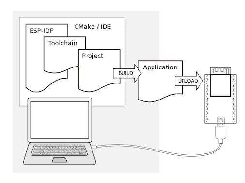
Software development environment setup
ESP-IDF SDK
ESP-IDF is Espressif’s open-source IoT development framework for ESP32/ESP8266 chips and a great way to begin with the Montic W02.
Preparation
- Hardware
- Montic W02 development board
- USB-C data cable
- Computer running Linux, Windows, or macOS
- Software
- ESP-IDF uses CMake and Ninja for builds.
Installation
Install and configure ESP-IDF either via the VS Code extension or manually. Using the VS Code extension is the quickest path.
Follow the official VS Code ESP-IDF installation guide or the simplified steps below.
-
Download and install Visual Studio Code
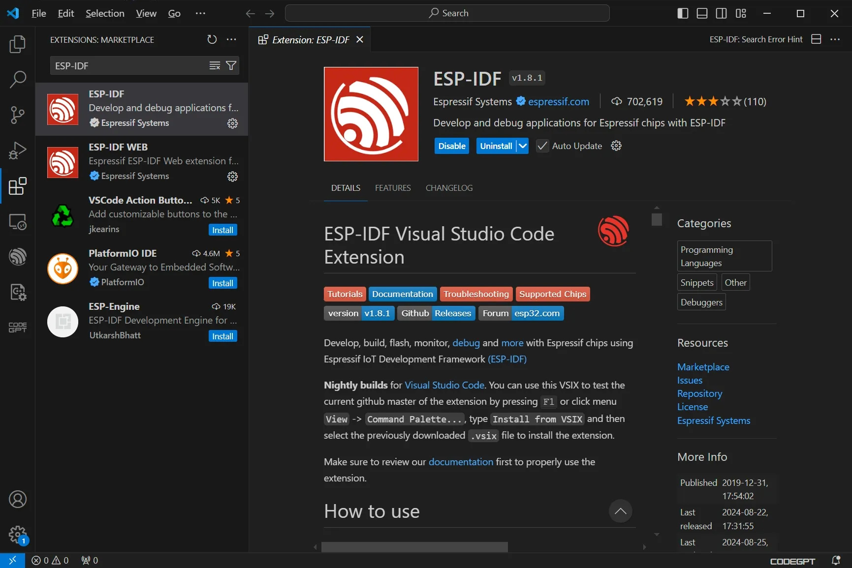
-
In VS Code, search for and install the ESP-IDF Extension
-
Configure ESP-IDF
In Visual Studio Code, select
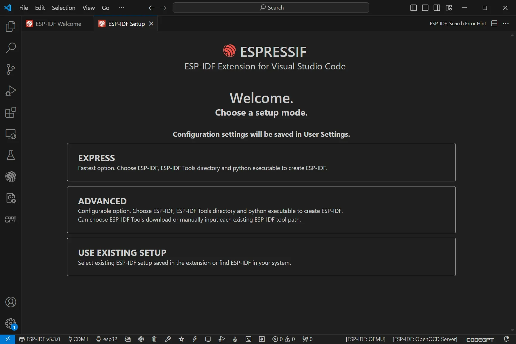
View -> Command Paletteor pressCtrl-Shift-P, then enterconfigure esp-idf extension. Select ESP-IDF: Configure ESP-IDF Extension. Choose where to save settings if prompted.Choose
Expressfor a quick install, select the latest release branch, and clickinstall. -
After installation, read the basic usage guide to learn how to configure, build, flash, and monitor your devices.
-
Install base packages for building with ESP-IDF (commands vary by distribution):
- Ubuntu and Debian:
Terminal window sudo apt-get install git wget flex bison gperf python3 python3-pip python3-venv cmake ninja-build ccache libffi-dev libssl-dev dfu-util libusb-1.0-0- CentOS 7 & 8:
Terminal window sudo yum -y update && sudo yum install git wget flex bison gperf python3 cmake ninja-build ccache dfu-util libusbx -
Download and install Visual Studio Code
-
Install the ESP-IDF Extension from the VS Code marketplace.
-
Configure ESP-IDF
In Visual Studio Code, open
View -> Command Palette(orCtrl-Shift-P), then enterconfigure esp-idf extensionand choose ESP-IDF: Configure ESP-IDF Extension. You can pick where to save the settings in the wizard.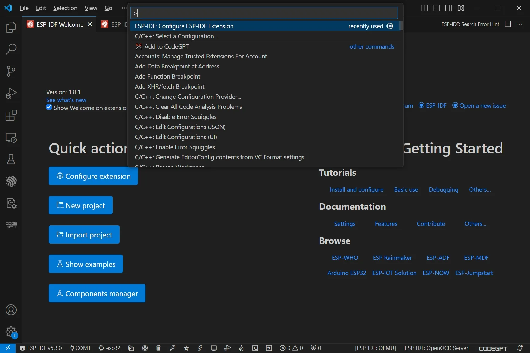
Select
Express, choose the latest release branch, and clickinstall.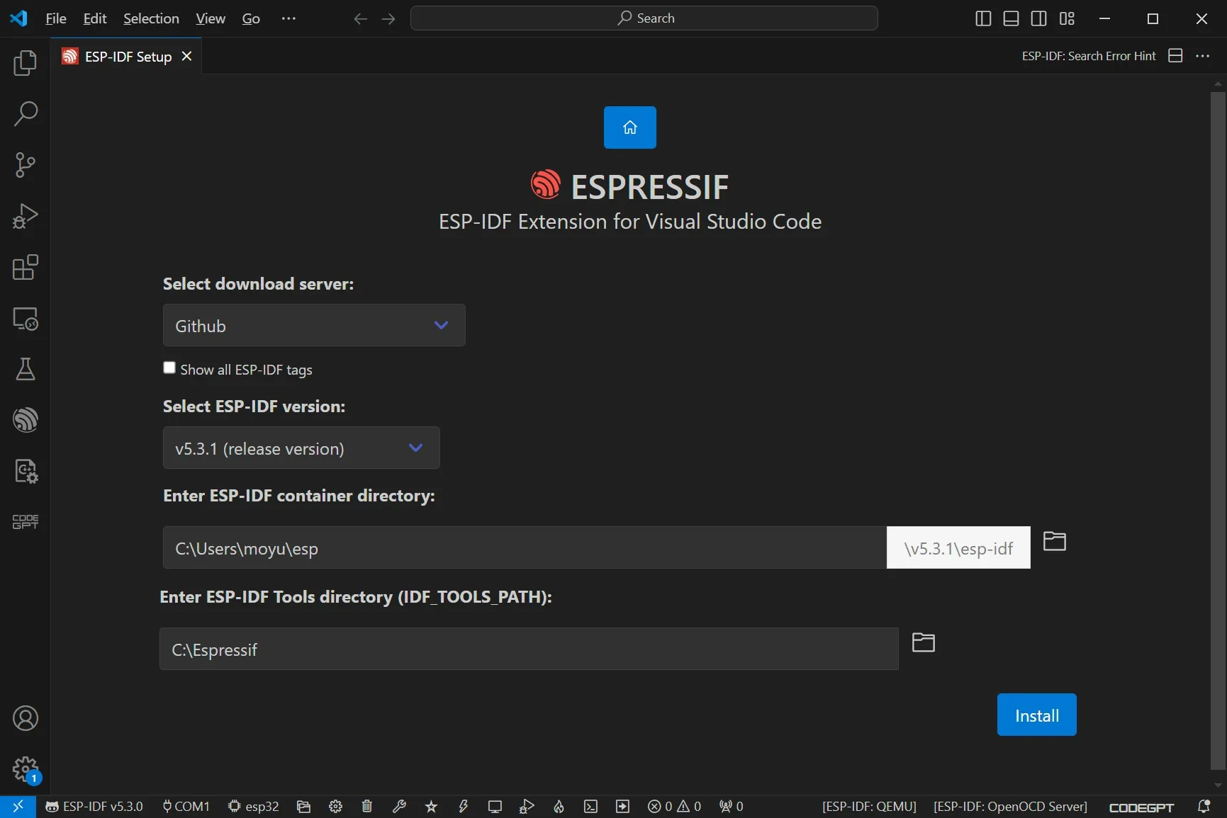
-
After installation, review the basic usage guide for configuring, building, flashing, and monitoring your devices.
-
ESP-IDF uses the system Python on macOS; also install CMake and Ninja.
- With Homebrew:
Terminal window brew install cmake ninja- Or with MacPorts:
Terminal window sudo port install cmake ninjaFor Apple Silicon users, if you see errors, check here.
-
Download and install Visual Studio Code
-
Install the ESP-IDF Extension in VS Code.
-
Configure ESP-IDF
In Visual Studio Code, open
View -> Command Palette(orCtrl-Shift-P), typeconfigure esp-idf extension, and choose ESP-IDF: Configure ESP-IDF Extension. Pick a location to save settings if needed.Select
Express, pick the latest release branch, and clickinstall. -
After installation, check the basic usage guide for configuring, building, flashing, and monitoring your devices.
Blink Demo (ESP-IDF)
With the environment set up, create a project to blink the RGB LED.
-
Create project
Open
ESP-IDF: Explorer, clickNew Project Wizard, choose the ESP32-C6, and clickChoose Template.Select the
Blinktemplate and clickCreate project using template blink.The new project structure looks like the example below. We will edit
main/blink_example_main.cnext.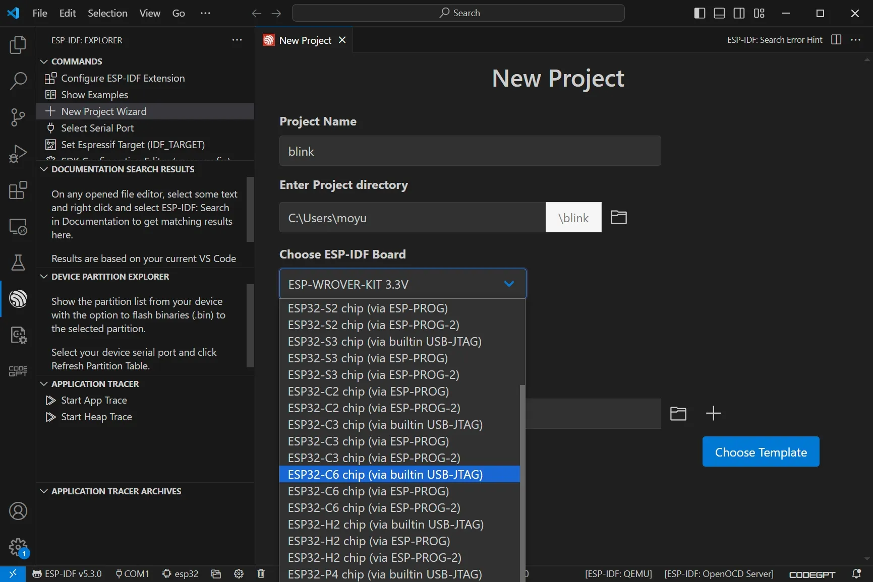
-
Set the LED pin
As described in the LED section, the Montic W02 drives the LED via GPIO15. Update the code to use the correct pin.
-
Build
After editing the code, configure the basics before building/flashing:
- Choose the correct serial port (
COMxon Windows,/dev/ttyUSBxxon Linux/macOS) - Choose the target chip: ESP32-C6
- Select UART flashing (the USB-C port provides the USB-to-UART bridge)
In VS Code, the toolbar options (red boxes) from left to right are:
- Select serial port (e.g.,
COM3) - Select target (
esp32c6) - Switch project
- SDK configuration editor (menuconfig)
- Clean (make clean)
- Build project
- Select flashing method (
UART) - Flash firmware
After configuration, click the build (wrench) icon and wait for compilation to finish. You should see output similar to the screenshot.
- Choose the correct serial port (
-
Flash
Click the flash (lightning) icon and wait for flashing to complete.
If flashing fails, adjust the options in the SDK configuration editor:
- Flash SPI mode: DIO
- Flash SPI Speed: 80MHz
- Flash Size: 8MB
- Enable “Detect flash size when flashing bootloader”
The final effect should match the animation.
Arduino
Thanks to the Arduino-ESP32 project, the Arduino IDE now supports ESP32-C6 boards, so we can program the Montic W02 with Arduino.
Set up the environment
-
Download and install the Arduino IDE.
-
Install the ESP32 Core
Open Arduino IDE and go to
File -> Preferences. In theAdditional Boards Manager URLsfield, add:Terminal window https://raw.githubusercontent.com/espressif/arduino-esp32/gh-pages/package_esp32_index.jsonClick “OK” to save.

-
Install ESP32 boards
Since Arduino IDE 1.6.4, you can install third-party platforms via the Boards Manager. Open
Tools -> Board -> Boards Manager, search foresp32, and install the Espressif ESP32 package.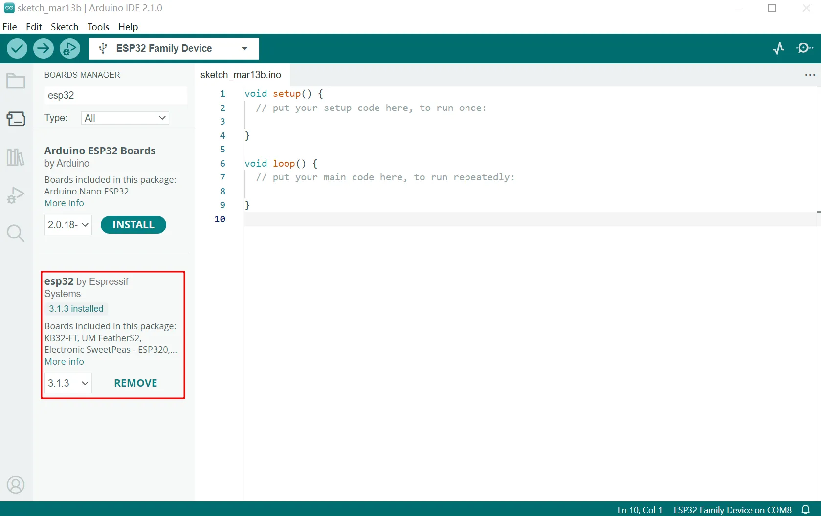
-
Add Montic W02 to Arduino
-
Navigate to:
- Windows:
%USERPROFILE%\AppData\Local\Arduino15\packages\esp32\hardware\esp32\VERSION - Linux/macOS:
$HOME/.Arduino15/packages/esp32/hardware/esp32/VERSION
- Windows:
-
Edit
boards.txtto add Montic W02 build/flash info.Montic W02 entry for boards.txt
boards.txt montic_w02.name=Montic W02montic_w02.bootloader.tool=esptool_pymontic_w02.bootloader.tool.default=esptool_pymontic_w02.upload.tool=esptool_pymontic_w02.upload.tool.default=esptool_pymontic_w02.upload.tool.network=esp_otamontic_w02.upload.maximum_size=1310720montic_w02.upload.maximum_data_size=327680montic_w02.serial.disableDTR=truemontic_w02.build.mcu=esp32c6montic_w02.build.core=esp32montic_w02.build.variant=montic_w02montic_w02.build.board=esp32c6montic_w02.build.arch=esp32montic_w02.build.f_cpu=160000000Lmontic_w02.build.flash_mode=qiomontic_w02.build.flash_freq=80mmontic_w02.build.flash_size=8MBmontic_w02.build.boot=qiomontic_w02.build.defines=-DARDUINO_USB_CDC_ON_BOOT=0 -DARDUINO_RUNNING_CORE=1 -DARDUINO_EVENT_RUNNING_CORE=1montic_w02.build.partitions=default_8MBmontic_w02.build.cdc_on_boot=0montic_w02.build.hwstring=Montic_W02montic_w02.build.usb_manufacturer=Montic Studiomontic_w02.build.usb_product=W02montic_w02.build.psram_type=qspimontic_w02.menu.DebugLevel.debug=Verbosemontic_w02.menu.DebugLevel.debug.build.code_debug=5montic_w02.menu.DebugLevel.verbose=Debugmontic_w02.menu.DebugLevel.verbose.build.code_debug=4montic_w02.menu.DebugLevel.info=Infomontic_w02.menu.DebugLevel.info.build.code_debug=3montic_w02.menu.DebugLevel.warning=Warningmontic_w02.menu.DebugLevel.warning.build.code_debug=2montic_w02.menu.DebugLevel.error=Errormontic_w02.menu.DebugLevel.error.build.code_debug=1montic_w02.menu.DebugLevel.none=Nonemontic_w02.menu.DebugLevel.none.build.code_debug=0montic_w02.menu.UploadSpeed.460800=460800montic_w02.menu.UploadSpeed.230400=230400montic_w02.menu.UploadSpeed.921600=921600montic_w02.menu.UploadSpeed.115200=115200montic_w02.menu.UploadSpeed.256000.windows=256000montic_w02.menu.UploadSpeed.512000.windows=512000montic_w02.menu.UploadSpeed.256000=256000montic_w02.menu.UploadSpeed.512000=512000montic_w02.menu.UploadSpeed.1000000.linux=1000000montic_w02.menu.UploadSpeed.1000000.macosx=1000000montic_w02.menu.UploadSpeed.1000000=1000000montic_w02.upload.port=37001montic_w02.upload.flags=--esp32c3 -
Then go to the Variants directory.
- Create a folder
montic_w02. - Inside, create
pins_arduino.h. - Add the pin mappings for the board:
pins_arduino.h content
#ifndef Pins_Arduino_h#define Pins_Arduino_h#include <stdint.h>#include "soc/soc_caps.h"#define PIN_RGB_LED 15// BUILTIN_LED can be used in new Arduino API digitalWrite() like in Blink.inostatic const uint8_t LED_BUILTIN = SOC_GPIO_PIN_COUNT + PIN_RGB_LED;#define BUILTIN_LED LED_BUILTIN // backward compatibility#define LED_BUILTIN LED_BUILTIN // allow testing #ifdef LED_BUILTIN// RGB_BUILTIN and RGB_BRIGHTNESS can be used in new Arduino API neopixelWrite()#define RGB_BUILTIN LED_BUILTIN#define RGB_BRIGHTNESS 64static const uint8_t TX = 29;static const uint8_t RX = 30;static const uint8_t SDA = 33;static const uint8_t SCL = 34;static const uint8_t SS = 13;static const uint8_t MOSI = 14;static const uint8_t MISO = 15;static const uint8_t SCK = 8;static const uint8_t A0 = 9;static const uint8_t A1 = 10;static const uint8_t A2 = 11;static const uint8_t A3 = 12;static const uint8_t D0 = 33;static const uint8_t D1 = 34;static const uint8_t D2 = 31;static const uint8_t D3 = 32;static const uint8_t D4 = 35;static const uint8_t D5 = 36;static const uint8_t D6 = 17;static const uint8_t D7 = 16;static const uint8_t D8 = 13;static const uint8_t D9 = 14;static const uint8_t D10 = 15;static const uint8_t D11 = 8;#endif /* Pins_Arduino_h */ - Create a folder
-
After adding the definitions, restart the Arduino IDE, go to Tools -> Board, and select Montic W02. You can also search for it in the board dropdown. If you encounter setup issues, refer to Espressif’s Arduino-ESP32 repository for the latest guidance.
Blink Demo (Arduino)
We’ll demonstrate a Blink example in Arduino. The ESP32 core already includes WS2812 support, making it easy to control the LED.
-
Open the
BlinkRGBexampleIn Arduino IDE, select Montic W02 as the target board, then open
File > Examples > ESP32 > GPIO > BlinkRGB.
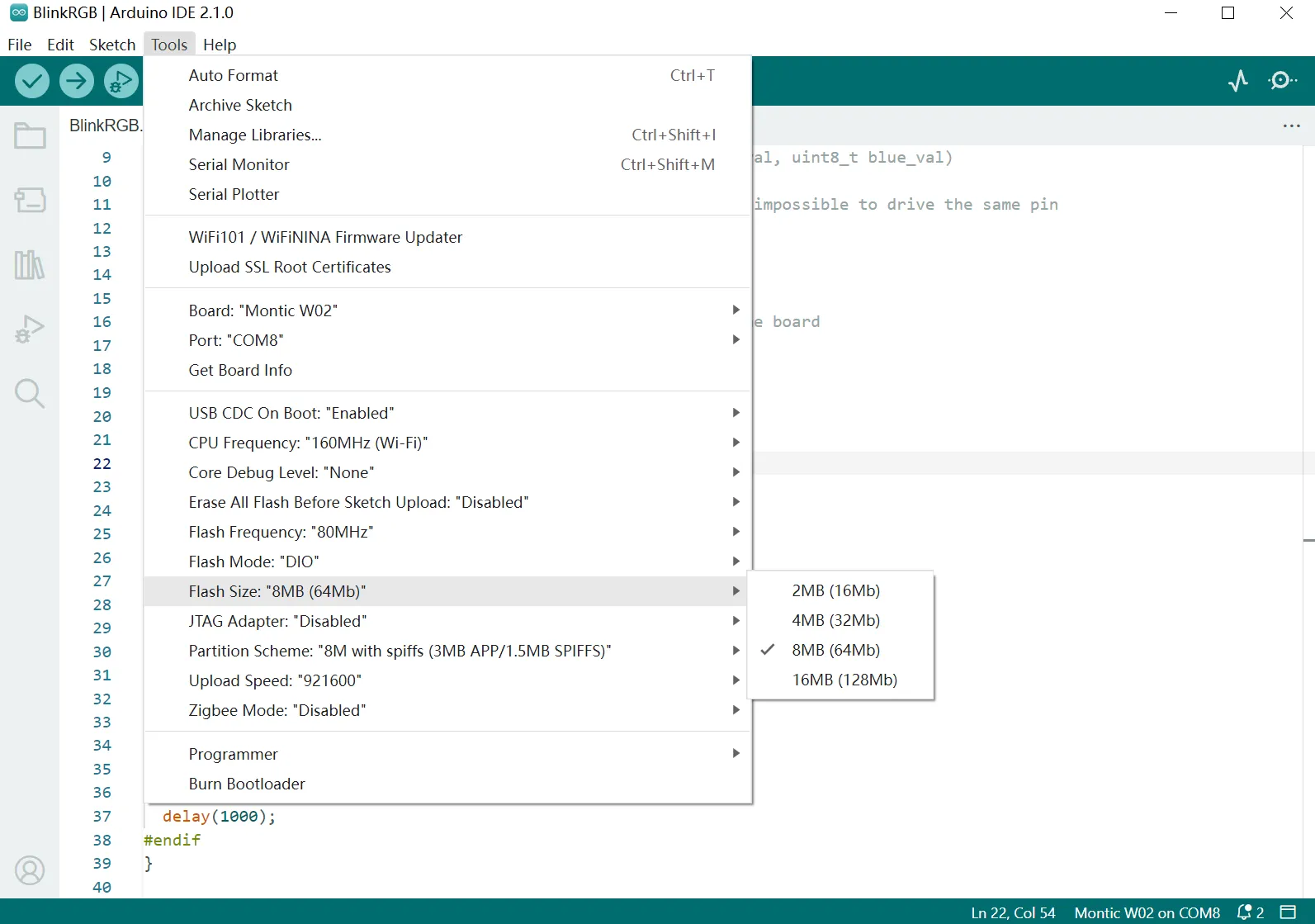
Update board settings as needed, such as Flash size.
-
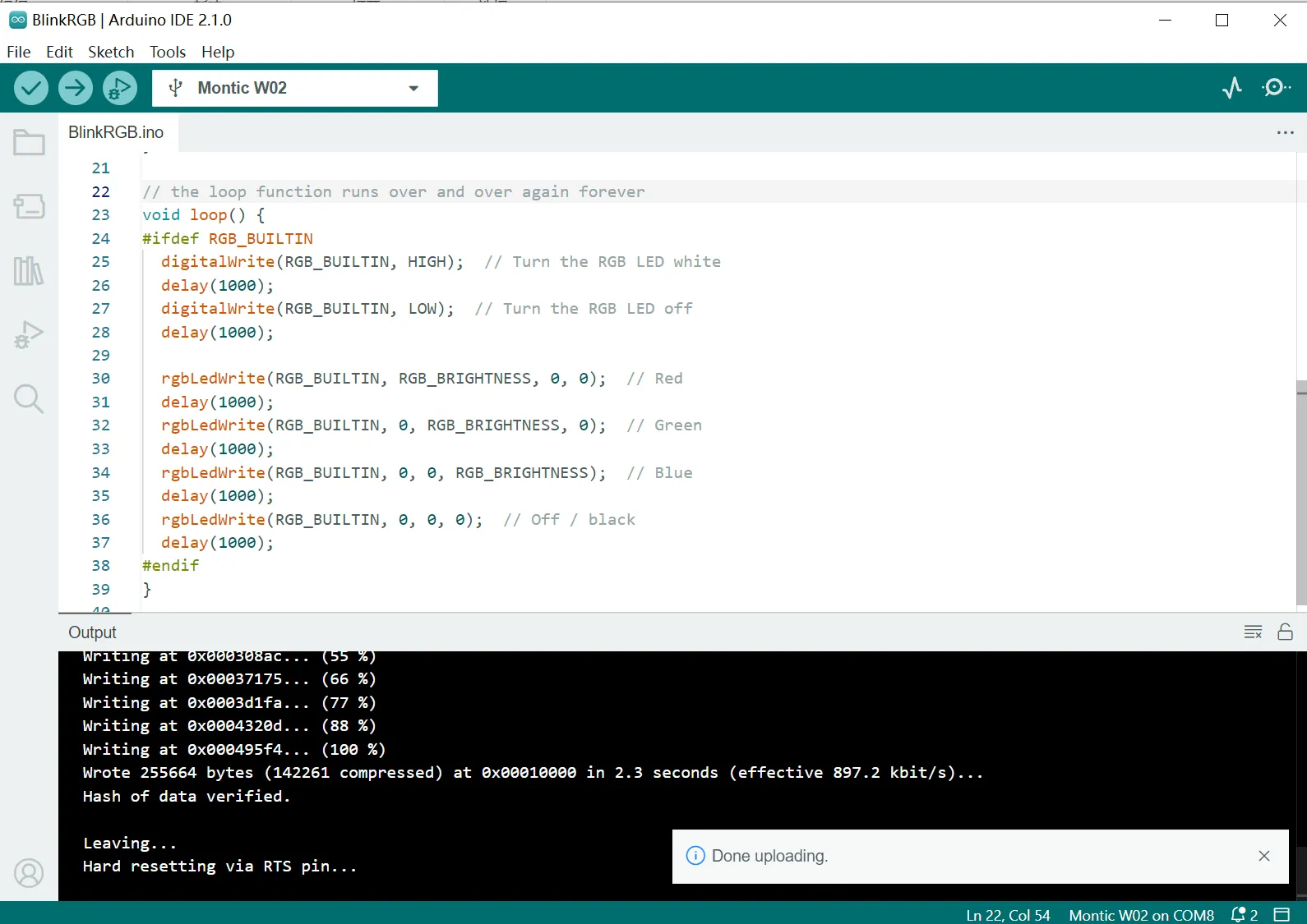
Upload the sketch
Click
Uploadto compile and flash. The process compiles first, then uploads to the Montic W02.
-
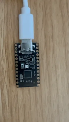
Blink!
The result is shown below: white, then off, then red/green/blue blinking in sequence.
Arduino is easy to learn with an active community—explore more examples to experience its capabilities.